OPERATING MINE
junio 5, 2017
The Ins and Outs of Wireline Core Retrieval Systems
Boart Longyear Improves Wireline Core Retrieval
Boart Longyear developed the wireline core retrieval system in 1958 and was the first diamond drilling exploration product manufacturer to offer this revolutionary system. The Genuine Q™ wireline system increased productivity on the work site and made tripping core from the bottom of the hole safer for the drilling assistant.
However, Boart Longyear has recently made improvements to the system, significantly increasing reliability and performance.
Primarily, wireline systems require a sample-receiving inner tube completely independent to the rod string, while located at the bottom of the rod string, in the outer tube behind the drill bit.
Mounted at the top of the inner tube assembly is the head assembly, which includes the critical latch mechanism required to hold the inner tube while receiving the core sample and to release the filled inner tube for wireline retrieval.
A device called the overshot is attached to a wireline cable and lowered or pumped into the hole until it captures the head assembly, allowing the inner tube to be pulled or hoisted back to the drill rig by use of a winch or hoist.
The Latch Seat
In order to receive the latches deployed from the head assembly, couplings are inserted into the drill string to provide an enlarged interior opening or seat. In the original system, the latch seat was formed by mating two couplings. The first coupling, mated to the drill rods above the inner tube, is known as the locking coupling. The lower coupling, known as the adapter coupling, mates between the locking coupling and the outer tube, below which the inner tube is housed, and in turn to the reaming shell and drill bit. The end face of the male end of the locking coupling serves as the load bearing face for the latch mechanism.
Unfortunately, all pivoting latch mechanisms require a significant amount of “play” or axial clearance in the latch seat to allow for the pivoting latch movement, which results in inner tube play and poor system performance in difficult ground. In fact, an inner tube with a wedged core, or an overfilled inner tube, can be sufficiently loaded up against the latch seat such that the latches are unable to pivot in retraction. This often results in a stuck tube, potentially requiring the costly retraction of the drill string.
In more recent Roller Latch™ systems, an improved integrated locking coupling eliminates the secondary joint and incorporates a mid-placed interior groove which serves as the latch seat. Additionally, roller latches drop away, eliminating the need for axial play and improving system performance in difficult ground.
Primarily, the latch seat must resist the reaction of the full thrust load from the drill whenever the driller is pushing through difficult, “blocky” ground. That is to say, when the core sample temporarily sticks or wedges in the inner tube (or when the tube is full), the thrust in the drill string (weight on bit) is fully resisted by the inner tube, the latch mechanism, and the locking coupling. However, the seat has a depth of about a third of the drill string thickness, which limits potential load-carrying capacity.
TIP: Although inner tubes are made from precision, cold-drawn mechanical tubing, they are limited in hardness and wear resistance. Core samples with hard, sharp edges can quickly develop grooving on the interior surface of the inner tube which, in turn, leads to severe core wedging or jamming. Boart Longyear’s chrome-plated inner tubes are a very effective solution, ensuring maximum core recovery and productivity.
Latch Mechanisms and Locking Coupling Material
The head assembly of the original Q system incorporated a latch mechanism consisting of a pair of pivoting latches, deployed by a wire “butterfly” spring and retracted by the impact with the bottom of a slot in the latch retracting case when retracted by the wireline overshot.
Now obsolete, these latches had only 8mm (5/16”) thickness, which produced a very small mating contact area on the latch seat. This resulted in contact pressure and material stresses which often exceeded the strength of the latch seat when drilling difficult ground conditions. In some cases, the latch seat material would yield and allow the latches to push into the locking coupling, resulting in a stuck tube. At a minimum, the high wear rate of the latch seat was a maintenance issue.
In 1998, Boart Longyear once again secured its position as the leading innovator in wireline technology by introducing the patented Link Latch™ mechanism. This innovation virtually eliminated “stuck tubes” by providing mechanical leverage during wireline retraction, directly pivoting the latches into the retracted position, whereas conventional technology attempted to indirectly push the latches while fighting poor mechanical leverage and interference with the latch seat.
Additionally, the latch thickness was doubled to 16mm (5/8”), which cut the latch seat contact pressure and stresses in half, improving wear life and reliability. However, inner tube play is required for the pivoting latches.
In 2012, the launch of Roller Latch technology included a significant upgrade to all Boart Longyear locking couplings. Heat-treated, alloy steel material provided substantial increases in strength (40% increase) and hardness (wear resistance). This provided much greater thrust capacity and reliability in pushing through difficult drilling conditions, but also significant improvements for other locking coupling features as discussed below.
TIP: Originally, latches were treated with a deep furnace case-hardening (carburizing) for wear resistance which proved excessively brittle in difficult drilling conditions, occasionally resulting in latch failures. The Link Latch mechanism included a significant improvement in wear resistance and reliability with a harder and thinner case-hardening (nitriding). Roller Latch technology utilizes bearing-quality, through-hardened, stainless-steel rollers for maximum wear resistance and reliability.
Locking Coupling Wear Pads
Situated at the top of the outer tube, the locking coupling can also act to stabilize the outer tube and reduce hole deviation. This is achieved through the addition of wear pads which act as a bearing surface against the drilled hole.
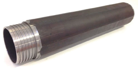
Boart Longyear offers two styles of locking couplings, “full-hole” and “stabilized.” While both are cut from the same high-quality alloy steel tubing material used for wireline drill rods, full-hole locking couplings have an over-sized outer diameter with four equispaced flats that are cold-drawn along each length.
While the annular area between the flats and the drilled hole provide passage for drilling fluid and cuttings, the over-sized rounded portions are induction case-hardened to provide hard, long-lasting, abrasion-resistant wear pads over the body length.
Full-hole locking couplings perform well in competent ground conditions where the hole is uniform and cuttings are fine. Conversely, poor ground conditions can significantly limit drilling performance and cuttings circulation, or generate excessive drill string torque or feed requirements.
TIP: Full-hole style outer tubes are also available to provide a significant increase in stiffness and directional control; recommended for competent ground conditions only.
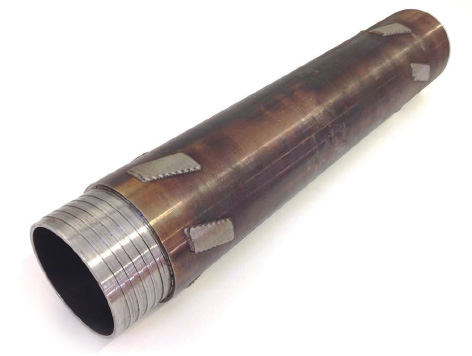
Stabilized locking couplings (formerly known as “conventional” style) utilize sets of wear pads consisting of tungsten carbide-bearing materials. Tungsten carbide offers wear resistance that is orders of magnitude greater than that of hardened steel, providing a reliable, longer-lasting bearing surface than the full-hole style.
Also, greater spacing between the wear pads, and in the annular area between the coupling body and the hole, ensures efficient passage of drilling fluids and cuttings in all ground conditions.
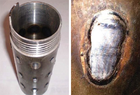
Originally, stabilized coupling wear pads were applied through a laborious manual process where welding technology was used to melt welding rods, consisting of tungsten carbide in a metal matrix known as “hard facing,” and bond the rod material to the coupling body.
A large amount needed to be added to be able to grind back down to a reasonably sized flat wear pad, and the resulting shape was difficult to control, which degraded the capacity to pass fluid and cuttings.
In addition, an excessive amount of heat was required, which softened the steel body and weakened the coupling. On some couplings, hard facing was also applied to the latch seat face for wear resistance, but due to the manual welding process, this could soften the underlying latch seat to the point where latches could protrude through the seat under normal loads.
Again, the launch of Roller Latch technology included another significant upgrade to all Boart Longyear™ stabilized locking couplings. Laser cladding technology enables the precise application of wear pads containing a significantly greater density of tungsten carbide and with very little heat.
Stabilized wear pads are provided in an efficient spiral shape, which promotes passage of drilling fluid and cuttings. Comparative laboratory wear testing has shown an improvement of over 10 times (testing to ASTM G65), which typically translates to more than double the wear life in the field.
Locking Coupling and Head Assembly Interaction
While Boart Longyear has improved the wear resistance of latches and latch seats, abrasive wear is caused by their interaction during normal drilling operations.
Significant relative rotational motion can occur between the Link Latch head assembly and the drill string when there is insufficient loading or mating contact friction. This can result in rapid wear between the latch seat and latches, as well as between the head assembly landing shoulder and the outer tube landing ring.
TIP: Wear between the landing shoulder and landing ring adds to the play of the inner tube, adversely affecting core recovery. Landing shoulders and landing rings are reversible, allowing for easy extension of wear life and to minimize play.
Locking couplings for the Link Latch head assembly are optionally available with a small drive key or “tang” which is an integral, partial extension of the male end shoulder which protrudes beside deployed latches. As such, rotation of the drill string will drive rotation of the head assembly in unison.
TIP: When tripping the inner tube into the drill string, if the inner tube latches land on top of the tang, they will not be able to deploy. A quick jump of the drill string (i.e., a short, sharp retraction and feed), preferably combined with a quick partial turn of the drill string, will re-seat the inner tube with the latches deploying beside the tang.
Conversely, the patented Roller Latch mechanism is self-locking in rotation. As the rollers are centrifugally deployed, if there is any relative rotational movement with the drill string, the rollers are wedged between the locking coupling and retracting case to ensure the head assembly is always driven with the drill string.
This self-locking action provides a significant increase in the wear life and reliability of the landing ring, landing shoulder, latch rollers, and the locking coupling latch seat.
Drill Rod String Connection
Locking couplings include both a male outer tube thread and a female wireline drill rod thread connection, in order to mate directly to the drill rod string.
The outer tube is significantly thicker and stiffer than the drill rods, and is stabilized by the drill bit, reaming shell, and locking coupling wear pads. Conversely, the drill rod string is supported only by the formation, and is subject to significant dynamic loading as a result of drilling loads, vibration, and system harmonics.
As such, the locking coupling connection is critical to performance in demanding drilling conditions, wherein the recently improved heat-treated material provides strength and wear resistance.
Boart Longyear’s proprietary Q and RQ™ wireline drill rod joints utilize tapered threads for easy make and break, and feature engineered thread forms, a precise interference fit, and a unique combination of heat treatments to maximize load strength and wear resistance.
Boart Longyear facilities produce these precision thread connections to exacting global standards, controlled to a proprietary master gauging system.
As is well understood across the wireline drilling industry, in order to avoid joint failures, never inter-mix genuine Boart Longyear drill rods, couplings, or adapters with products produced by unlicensed third parties.
Ready to look into Boart Longyear's rods?
[pardot-form id="1793" width="600px" title="Download Coring Rods and Casing Catalog"]
This article originally appeared in Coring Magazine.


